


Model
SEN05221-05SKU
40546Brand
KomatsuAvailability:
Ready for Instant DownloadThis manual does not contain engine information. Depending on the engine used, see the manuals: SAA4D107E-1: SEN00161-24
$25.00
Language
EnglishModel of Truck
PC200LC-8E0, PC200-8E0Region
JapanType of Document
Workshop ManualType of Truck
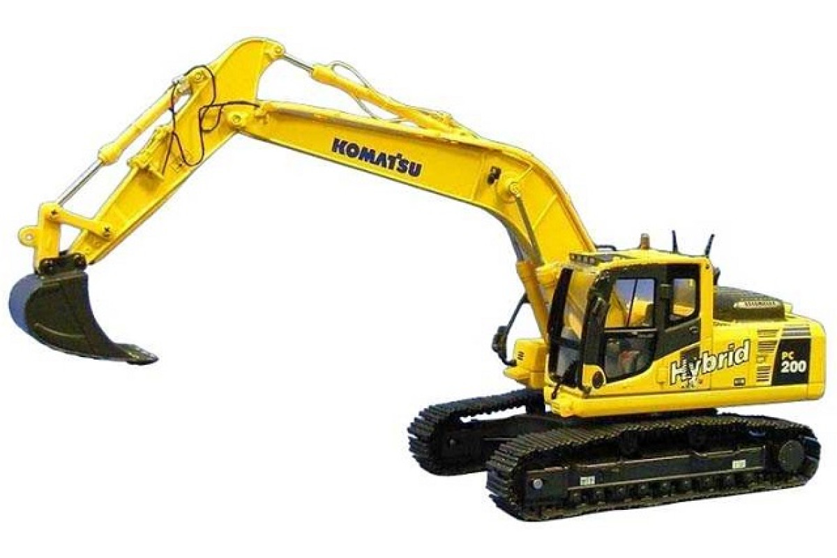
Hybrid ExcavatorIllustrated factory Workshop Manual for Komatsu Hybrid Excavators Models PC200-8E0 and PC200LC-8E0.
This manual will assist you in diagnosing, repairing, and adjusting for your hybrid excavator.
You can use a Windows, Mac, or Android device to view this manual. You only need to have a PDF reader installed.
Covered Models (Japan):
PC200-8E0 (SN: 01001-)
PC200LC-8E0 (SN: 01001-)
Format: PDF, 1284 pages
Language: English
Table of Contents:
Index and Foreword
Index
Composition of shop manual
Table of contents
Foreword and general information
Safety notice
How to read the shop manual
Explanation of terms for maintenance standard
Handling of hydraulic components
Method of disassembling and connecting push-pull type coupler
Handing of electric equpment
How to read electric wire code
Precautions when carrying out work
Handling of hybrid devices and high-voltage wirings
Standard tightening torque table
Conversion table
Specification
Specification and technical data
Outline of hybrid system
Specification dimension drawings
Working range diagram
Specifications
Weight table
Table of fuel, coolant and lubricants
Structure,function and maintenance standard
Engine and cooling system
Engine related parts
Radiator, oil cooler, aftercooler and fuel cooler
Hyblid Relation
Configuration and safety functions of hybrid system
Cooling system of hybrid component
Motor generator
Swing electric motor
Electric control unit
High-voltage wiring (power cable)
Power train
Final drive
Swing machinery
Swing circle
Undercarriage and frame
Track frame and recoil spring
Idler
Carrier roller
Track roller
Track shoe
Hydraulic system, Part 1
Hydraulic components layout drawing
Hydraulic tank and filter
Hydraulic pump
Hydraulic system, Part 2
Control valve
CLSS
Functions and operation by valve
Hydraulic system, Part 3
Center swivel joint
Travel motor
PPC valve
Valve control
Solenoid valve
Accumulator
Hydraulic cylinder
Work equipment
Dimensions of components
Cab and its attachments
Air conditioner piping
Electrical system
Engine control
Electrical control system
Monitor system
Sensors
KOMTRAX system
Standard value table
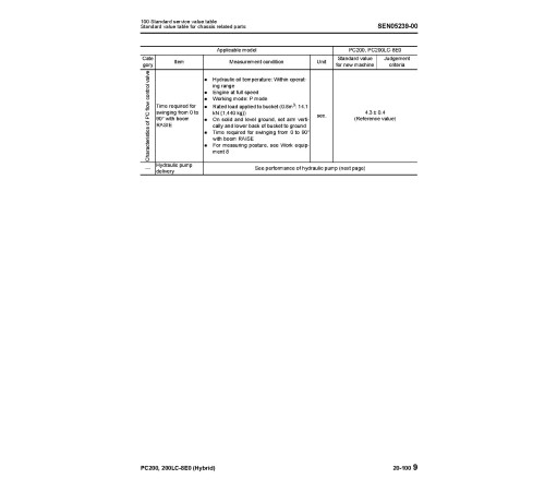
Standard service value table
Standard value table for engine related parts
Standard value table for chassis related parts
Testing and adjusting
Testing and adjusting, Part 1
Tools for testing, adjusting and troubleshooting
Testing engine speed
Testing boost pressure
Checking exhaust gas color
Adjusting valve clearance
Testing compression pressure
Testing blowby pressure
Testing engine oil pressure
Handling fuel system parts
Releasing remaining pressure from fuel system
Testing fuel system pressure
Cylinder cut-out test mode operation
No injection cranking operation
Testing fuel return rate and leakage
Bleeding air from fuel circuit
Testing fuel circuit for leakage
Handling of controller high-voltage circuit
Testing and adjusting air conditioner compressor belt tension
Replacement of fan belt
Testing swing circle bearing clearance
Testing and adjusting track tension .
Testing and adjusting hydraulic oil pressure in work equipment and trave
Testing source pressure of control circuit
Testing and adjusting oil pressure in pump PC control circuit
Testing and adjusting oil pressure in pump LS control circuit
Testing solenoid valve output pressure
Testing PPC valve output pressure
Adjusting play of work equipment and swing PPC valves
Checking parts which cause hydraulic drift of work equipment
Releasing remaining pressure from hydraulic circuit
Testing oil leakage
Bleeding air from each part
Checking cab tipping stopper
Adjusting mirrors
Angle adjustment of rear view camera
Testing swing brake
Cleaning and replacement of oil filter of electric swing motor
Operation check of swing emergency stop switch
Testing and adjusting, Part 2
Special functions of machine monitor
Testing and adjusting, Part 3
Handling voltage circuit of engine controller
Precautions related to hybrid machines
Preparation work for troubleshooting of electrical system
Procedure for testing diodes
Pm Clinic service
Troubleshooting
Failure code table and fuse locations
Failure code table
Fuse locations
General Information on troubleshooting
Points to remember when troubleshooting
Sequence of events in troubleshooting
Check before troubleshooting
Classification and procedures for troubleshooting
Probable problems and troubleshooting No
Information in troubleshooting table
Connection table for connector pin numbers
T-adapter and box table
Troubleshooting by failure code
Troubleshooting of electrical system (E-mode) SEN05
Before performing troubleshooting of electrical system
Information in troubleshooting table
Troubleshooting of electrical system (E-mode) SEN05
Before performing troubleshooting of electrical system
Information in troubleshooting table
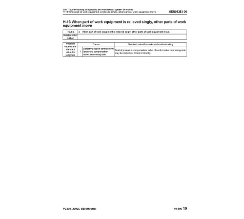
Troubleshooting of hydraulic and mechanical system (H-mode) SEN
System diagram of hydraulic and mechanical system
Information in troubleshooting table
Troubleshooting of engine (S-mode) SEN
Method of using troubleshooting chart
Troubleshooting of Hybrid system (Y-mode)
Precautions related to hybrid machine
Disassembly and assembly
General information on disassembly and assembly
How to read this manual
Precautions related to hybrid machine
Coating materials list
Special tools list
Sketches of special tools
Engine and cooling system
Removal and installation of fuel supply pump assembly
Removal and installation of fuel injector assembly
Removal and installation of engine front seal
Removal and installation of engine rear seal
Removal and installation of cylinder head assembly
Removal and installation of radiator assembly
Removal and installation of hydraulic oil cooler assembly
Removal and installation of aftercooler assembly
Removal and installation of fuel cooler assembly
Removal and installation of engine/motor-generator/hydraulic pump assembly
Removal and installation of fuel tank assembly
Hyblid Relation
Draining and adding coolant and bleeding air for hybrid system
Removal and installation of hybrid radiator assembly
Removal and installation of water pump assembly for hybrid system
Removal and installation of inverter assembly
Removal and installation of inverter and capacitor assembly
Draining and adding generator lubricating oil
Removal and installation of tandempump assembly
Removal and installation of motor-generator and housing assembly
Removal and installation of swing electric motor assembly
Power train
Removal and installation of final drive assembly
Disassembly and assembly of final drive assembly.
Removal and installation of \\"swing electric motor and swing machinery assemb
Disassembly and assembly of swing machinery assembly
Removal and installation of swing circle assembly
Undercarriage and frame
Disassembly and assembly of carrier roller assembly
Disassembly and assembly of track roller assembly
Disassembly and assembly of idler assembly
Disassembly and assembly of recoil spring assembly
Removal and installation of sprocket
Expansion and installation of track shoe assembly
Removal and installation of revolving frame assembly
Removal and installation of counterweight assembly
Hydraulic system
Removal and installation of centerswivel joint assembly
Disassembly and assembly of center swivel joint assembly
Removal and installation of hydraulic tank assembly
Removal and installation of control valve assembly
Disassembly and assembly of control valve assembly
Removal and installation of hydraulic pump assembly
Removal and installation of oil sealin hydraulic pump input shaft
Disassembly and assembly of work equipment PPCvalve assembly
Disassembly and assembly of travel PPC valve assembly
Disassembly and assembly of hydraulic cylinder assembly
Work equipment Body
Removal and installation of work equipment assembly
Cab and its attachments
Removal and installation of operator's cab assembly
Removal and installation of operator cab glass (stuck glass)
Removal and installation of front window assembly
Removal and installation of floor frame assembly
Removal and installation of air conditioner unit assembly
Electric system
Removal and installation of KOMTRAX terminal
Removal and installation of monitor assembly
Removal and installation of pump controller assembly
Removal and installation of enginecontroller assembly
Diagrams and Drawings
Hydraulic diagrams and drawings
Hydraulic circuit diagram
Electrical diagrams and drawings
Electrical circuit diagram
Connector list and sterogram.
General
Language
EnglishModel of Truck
PC200LC-8E0, PC200-8E0Region
JapanType of Document
Workshop ManualType of Truck
Hybrid ExcavatorReviews: 0
There are no reviews for this product.
Questions: 0
No questions about this product.
