

Model
UEBM001801SKU
40247Brand
KomatsuAvailability:
Ready for Instant DownloadThis manual does not contain engine information. Depending on the engine used, see the manuals: SAA6D140E-3: SEBM022213
$25.00
Language
EnglishModel of Truck
PC750LC-6K, PC750SE-6KRegion
United KingdomType of Document
Workshop ManualType of Truck
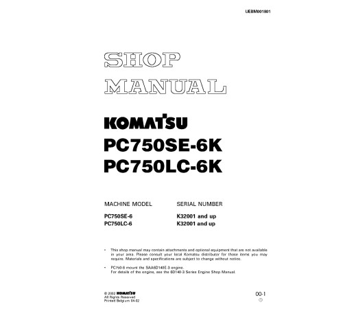
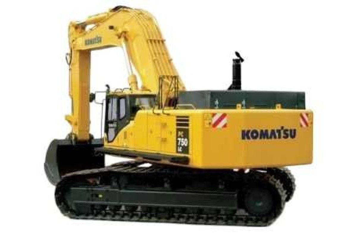
Crawler ExcavatorIllustrated factory Workshop Manual for Komatsu Crawler Excavators Models PC750LC-6K and PC750SE-6K.
This manual will assist you in diagnosing, repairing, and adjusting for your crawler excavator.
You can use a Windows, Mac, or Android device to view this manual. You only need to have a PDF reader installed.
Covered Models (United Kingdom):
PC750LC-6K (SN: K32001-)
PC750SE-6K (SN: K32001-)
Format: PDF, 701 pages
Language: English
Table of Contents:
GENERAL
SPECIFICATION DRAWINGS
FUEL, COOLANT AND LUBRICANTS
PTO
PTO LUBRICATION SYSTEM
POWER TRAIN SWING MACHINERY SWING CIRCLE
FINAL DRIVE
TRACK FRAME AND RECOIL SPRING
IDLER CARRIER ROLLER
TRACK ROLLER
TRACK SHOE ( 1/ 2)
( 2/ 2)
MOTOR GREASE PUMP
HYDRAULIC TANK
HYDRAULIC PUMP
LINE OIL FILTER
PILOT OIL FILTER
DRAIN OIL FILTER
L. H. 5- SPOOL CONTROL VALVE
R. H. 4- SPOOL CONTROL VALVE
STRAIGHT- TRAVEL VALVE
SWING MOTOR
CENTER SWIVEL JOINT
TRAVEL MOTOR
PPC CONTROL RELIEF VALVE
SAFETY LOCK VALVE
PPC ACCUMULATOR
VALVE CONTROL
WORK EQUIPMENT, SWING PPC VALVE
TRAVEL PPC VALVE
SOLENOID VALVE
HYDRAULIC CYLINDER
WORK EQUIPMENT
DIMENSIONS OF WORK EQUIPMENT
AIR CONDITIONER
ENGINE CONTROL
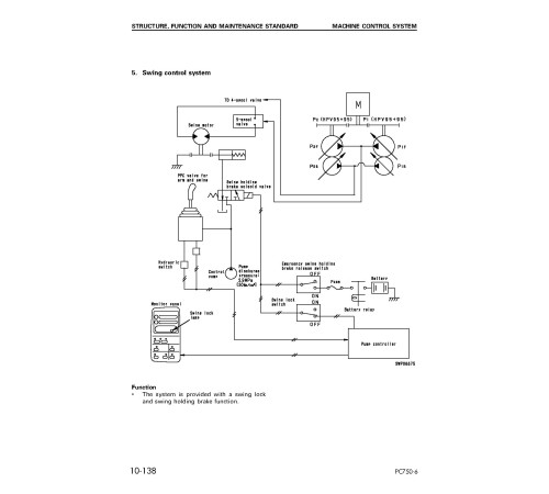
MACHINE CONTROL SYSTEM
MONITOR SYSTEM
SENSORS
TESTING AND ADJUSTING
STANDARD VALUE TABLE FOR ENGINE
STANDARD VALUE TABLE FOR CHASSIS
STANDARD VALUE TABLE FOR ELECTRICAL PARTS
TOOLS FOR TESTING, ADJUSTING, AND TROUBLESHOOTING
MEASURING AIR SUPPLY PRESSURE ( BOOST PRESSURE)
MEASURING EXHAUST TEMPERATURE
MEASURING EXHAUST COLOR
ADJUSTING VALVE CLEARANCE
MEASURING BLOW- BY PRESSURE
MEASURING COMPRESSION PRESSURE
MEASURING ENGINE OIL PRESSURE
HANDLING EQUIPMENT IN FUEL CIRCUIT
RELEASING REMAINING PRESSURE IN FUEL SYSTEM
MEASURING FUEL PRESSURE
REDUCED CYLINDER MODE OPERATION FOR ENGINE
BLEEDING AIR FROM FUEL CIRCUIT
CHECKING FOR LEAKAGE IN FUEL CIRCUIT
TESTING AND ADJUSTING ALTERNATOR BELT TENSION
TESTING AND ADJUSTING FAN BELT TENSION
TESTING AND ADJUSTING AIR CONDITIONER COMPRESSOR DRIVE BELT TENSION
HANDLING ENGINE CONTROL- LER HIGH VOLTAGE CIRCUIT
ADJUSTING ENGINE SPEED SENSOR
TESTING AND ADJUSTING HYDRAULIC PRESSURE IN WORK EQUIPMENT, SWING, TRAVEL CIRCUIT
TESTING AND ADJUSTING CONTROL PUMP CIRCUIT OIL PRESSURE
TESTING AND ADJUSTING PISTON PUMP CONTROL PRESSURE
MEASURING SERVO PISTON STROKE
MEASURING PPC VALVE OUT- PUT PRESSURE
TESTING SOLENOID VALVE OUTPUT PRESSURE
ADJUSTING WORK EQUIP- MENT, SWING PPC VALVE
TESTING TRAVEL DEVIATION
TESTING LOCATIONS CAUSING HYDRAULIC DRIFT OF WORK EQUIPMENT
MEASURING OIL LEAKAGE
TESTING CLEARANCE OF SWING CIRCLE BEARING
TESTING AND ADJUSTING TRACK SHOE TENSION
BLEEDING AIR
RELEASING REMAINING PRESSURE IN HYDRAULIC CIRCUIT
PROCEDURE FOR CHECKING DIODE
POINTS TO REMEMBER WHEN TROUBLESHOOTING
SEQUENCE OF EVENTS IN TROUBLESHOOTING POINTS TO REMEMBER WHEN CARRYING OUT MAINTENANCE CHECKS BEFORE TROUBLESHOOTING
CONNECTOR TYPES AND MOUNTING LOCATIONS
CONNECTION TABLE FOR CONNECTOR PIN NUMBERS
EXPLANATION OF CONTROL MECHANISM FOR ELECTRICAL SYSTEM
DISPLAY METHOD AND SPECIAL FUNCTIONS OF MONITOR PANEL
METHOD OF USING JUDGEMENT TABLE
METHOD OF USING TROUBLESHOOTING CHARTS
DETAILS OF TROUBLESHOOTING AND TROUBLESHOOTING PROCEDURE
ACTION TAKEN BY CONTROLLER WHEN ABNORMALITY OCCURS AND PROBLEMS ON MACHINE
N- 1 [ E117, E118 occur at same time ] Monitor panel communication abnormality
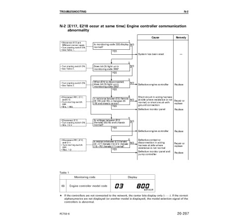
N- 2 [ E117, E218 occur at same time ] Engine controller communication abnormality
N- 3 [ E118, E955 occur at same time ] Pump controller communication abnormality
ACTION TAKEN BY CONTROLLER AND CONDITION OF MACHINE WHEN ERROR CODE IS DISPLAYED
ACTION TAKEN BY CONTROLLER AND CONDITION OF MACHINE WHEN ERROR CODE IS DISPLAYED
E- 1 [ E91b ] ( Abnormality in engine speed Ne sensor system) is displayed
E- 2 [ E91C ] ( Abnormality in engine G rotation sensor system) is displayed
E- 3 [ E920 ] ( Abnormality in model selection system) is displayed
E- 4 [ E922 ] ( Engine overrun) is displayed
E- 5 [ E924 ] ( Drop in engine oil pressure) is displayed
E- 6 [ E931 ] ( Abnormality in fuel control dial sensor system) is displayed
E- 7 [ E934 ] ( Abnormality in engine water high- temperature sensor system) is displayed
E- 8 [ E936 ] ( Abnormality in engine oil pressure switch system) is displayed
E- 9 [ E93C ] ( Abnormality in boost pressure sensor system) is displayed
E- 10 [ E93d ] ( Abnormality in fuel temperature sensor system) is displayed
E- 11 [ E954 ] ( Short circuit in starting switch C system) is displayed
[ E955 ] ( Abnormality in network system) is displayed
E- 13 [ E956 ] ( Power source system abnormality 1) is displayed
E- 14 [ E957 ] ( Power source system abnormality 2) is displayed
[ E95A ] ( Abnormality in fuel injection amount adjustment switch signal) is displayed
E- 16 [ E96A ] ( Abnormality in engine water low- temperature sensor system) is displayed
E- 17 [ E970 ] ( Excess current in fuel supply pump PCV1 system) is displayed
E- 18 [ E971 ] ( Excess current in fuel supply pump PCV2 system) is displayed
E- 19 [ E974 ] ( Disconnection in fuel supply pump PCV1 system) is displayed
E- 20 [ E975 ] ( Disconnection in fuel supply pump PCV2 system) is displayed
E- 21 [ E977 ] ( Abnormality in common rail fuel pressure sensor system) is displayed
E- 22 [ E979 ] ( Common rail fuel high pressure abnormality 1) is displayed [ E97A ] ( Common rail fuel high pressure abnormality 2) is displayed
E- 23 [ E97b ] ( Fuel supply pump non- force feed 1) is displayed [ E97C ] ( Fuel supply pump non- force feed 2) is displayed
E- 24 [ E97d ] ( Abnormality in common rail fuel pressure) is displayed
E- 25 [ E980 ] ( Defective engine controller) is displayed
E- 26 [ E981 ] ( Disconnection in No. 1 fuel injector system) is displayed
E- 27 [ E982 ] ( Disconnection in No. 2 fuel injector system) is displayed
E- 28 [ E983 ] ( Disconnection in No. 3 fuel injector system) is displayed
E- 29 [ E984 ] ( Disconnection in No. 4 fuel injector system) is displayed
E- 30 [ E985 ] ( Disconnection in No. 5 fuel injector system) is displayed
E- 31 [ E986 ] ( Disconnection in No. 6 fuel injector system) is displayed
E- 32 [ E98A ] ( Short circuit in No. 1, No. 2, No. 3 fuel injector system) is displayed
E- 33 [ E98b ] ( Short circuit in No. 3, No. 4, No. 5 fuel injector system) is displayed
TROUBLESHOOTING OF PUMP CONTROLLER SYSTEM ( C MODE)
POINTS TO REMEMBER WHEN TROUBLESHOOTING CONTROLLER SYSTEM
ACTION TAKEN BY CONTROLLER WHEN ABNORMALITY OCCURS AND PROBLEMS ON MACHINE
JUDGEMENT TABLE FOR PUMP CONTROLLER AND HYDRAULIC RELATED PARTS
POINTS TO REMEMBER WHEN TROUBLESHOOTING CONTROLLER SYSTEM
ACTION TAKEN BY CONTROLLER WHEN ABNORMALITY OCCURS AND PROBLEMS ON MACHINE
JUDGEMENT TABLE FOR PUMP CONTROLLER AND HYDRAULIC RELATED PARTS
C- 1 Abnormality in controller power source system ( controller LED is OFF)
C- 1 Related electrical circuit diagram
TROUBLESHOOTING C- 2
C- 2 [ E232 ] Short circuit in pump TVC solenoid system is displayed
TROUBLESHOOTING C- 2 C- 2 Related electrical circuit diagram TROUBLESHOOTING C- 3
C- 3 [ E233 ] Disconnection in pump TVC solenoid system is displayed
TROUBLESHOOTING C- 3 C- 3 Related electrical circuit diagram TROUBLESHOOTING C- 4
C- 4 [ E203 ] Short circuit in swing holding brake solenoid system is displayed
TROUBLESHOOTING C- 4 C- 4 Related electrical circuit diagram TROUBLESHOOTING C- 5
C- 5 [ E213 ] Disconnection in swing holding brake solenoid system is displayed
TROUBLESHOOTING C- 5 C- 5 Related electrical circuit diagram TROUBLESHOOTING C- 6
C- 6 [ E201 ] Short circuit in CO cancel solenoid system is displayed
C- 6 Related electrical circuit diagram
TROUBLESHOOTING C- 7
C- 7 [ E211 ] Disconnection in CO cancel solenoid system is displayed
C- 7 Related electrical circuit diagram
TROUBLESHOOTING C- 8
C- 8 [ E202 ] Short circuit in straight- travel solenoid system is displayed
C- 8 Related electrical circuit diagram
TROUBLESHOOTING C- 9
C- 9 [ E212 ] Disconnection in straight- travel solenoid system is displayed
C- 9 Related electrical circuit diagram
TROUBLESHOOTING C- 10
C- 10 [ E204 ]
General
Language
EnglishModel of Truck
PC750LC-6K, PC750SE-6KRegion
United KingdomType of Document
Workshop ManualType of Truck
Crawler ExcavatorReviews: 0
There are no reviews for this product.
Questions: 0
No questions about this product.
