

$10.00
Language
EnglishModel of Truck
PC1250-7, PC1250LC-7, PC1250SP-7Region
JapanType of Document
Field Assembly ManualType of Truck
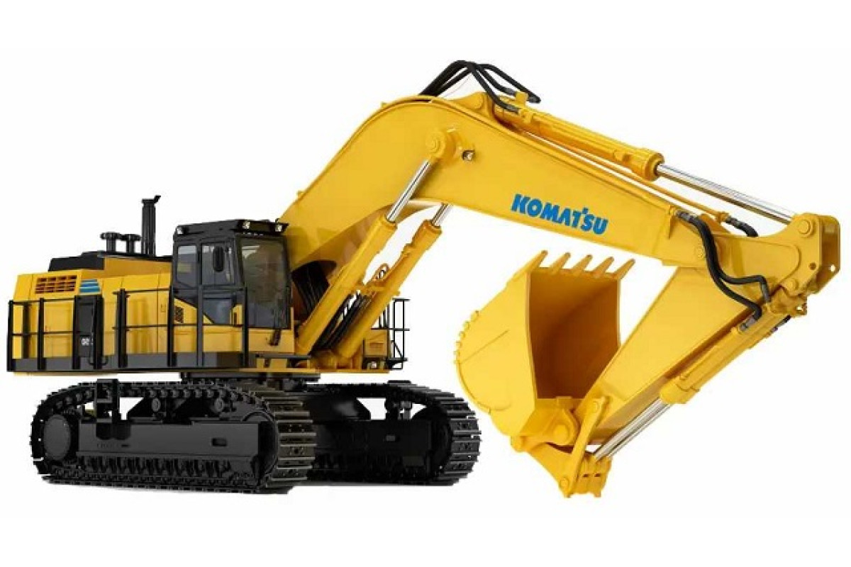
Crawler ExcavatorIllustrated factory Field Assembly Manual for Komatsu Crawler Excavators Models PC1250-7, PC1250LC-7 and PC1250SP-7.
This manual will assist you in for your crawler excavator.
You can use a Windows, Mac, or Android device to view this manual. You only need to have a PDF reader installed.
Covered Models (Japan):
PC1250-7 (SN: 20001-)
PC1250LC-7 (SN: 20001-)
PC1250SP-7 (SN: 20001-)
Format: PDF, 192 pages
Language: English
Table of Contents:
FOREWARD
SPECIFICATIONS
PRECAUTIONS FOR FIELD ASSEMBLY
ASSEMBLING PROCEDURES, APPLICABLE EQUIPMENT AND SCHEDULE
KIT LAYOUT DIAGRAM
TRANSPORTATION
LIST OF ASSEMBLING TOOLS TO BE BROUGHT IN FIELD
TIGHTENING TORQUE
COATING MATERIALS
LIST OF PARTS SENT INDIVIDUALLY
A. ASSEMBLY OF CHASSIS
A-1. Installation of Track Frame
A-2. Supplying Grease to Swing Circle
A-3. Assembly of Upper Structure and Undercarriage
A-4. Installation of Travel Piping
A-5. Installation of Travel Piping Cover
A-6. Installation of Swivel Travel Piping
A-6. Sticking Sheets (Counterweight)
A-7. Installation of Counterweight
A-8. Installation of Steps
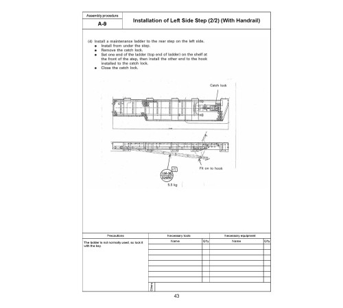
A-9. Installation of Left Side Step (With Handrail)
A-10. Installation of Right Side Step
A-11. Installation of Handrail
A-12. Installation of Radiator Cover
A-13. Installation of Intake Air Cap and Muffler Tail Pipe
A-14. Installation of Left Rear-view Mirror
A-15. Installation of Right Rear-view Mirror
A-16. Preparation for Bleeding Air from Travel Motor
A-17. Procedure for Bleeding Air from Hydraulic Circuit
A-18. Tightening Swing Circle Mounting Bolts Permanently
A-19. Testing and Adjusting Track Link
A-20. Inspection of Oil Amount and Water Amount
A-21. Parts To Be Touched Up After Field Assembly
B.ASSEMBLING OF WORK EQUIPMENT OF BACKHOE
B-1. Boom Foot Pin, Boom Cylinder Foot Pin
B-2. Installation of Boom Cylinder Foot
B-3. Installation of Boom Cylinder Hoses
B-4. Installation of Boom Assembly
B-5. Installation of Boom Cylinder
B-6. Installation of Boom Hoses (Between Chassis and Boom)
B-7. Installation of Arm Cylinder
B-8. Installation of Arm Cylinder Hoses
B-9. Installation of Arm Assembly
B-10. Installation of Bucket Cylinder Hoses (Between Boom and Bucket Cylinder)
B-11. Installation of Bucket Assembly
B-12. Clearance Standards for Work Equipment Mount
B-13. Installation of Work Equipment Grease Piping
B-14. Procedure for Bleeding Air from Travel Motor
B-15. Bleeding Air from Swing Motor
B-16. Bleeding Air from Cylinder
B-17. Installation of Work Equipment Electric Wiring
B-18. Installation of Floor Mat
B-19. Greasing Assembled Work Equipment
M.PROCEDURE FOR INSPECTION AND MAINTENANCE AFTER COMPLETION OF ASSEMBLY
M-1. Reassembly of Return Filter (Standard Part o Flushing Part)
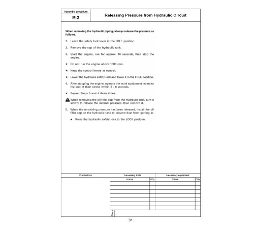
M-2. Releasing Pressure from Hydraulic Circuit
M-3. Installation of Work Equipment Flushing Tube
M-4. Flushing Hydraulic Circuit
M-5. Reassembly of Pilot Filter (Flushing Part o Standard Part)
C. PROCEDURE FOR ASSEMBLING WORK EQUIPMENT OF LOADING SHOVEL
TRANSPORTATION POSTURE (ONLY WORK EQUIPMENT)
LIST OF PARTS SENT INDIVIDUALLY
C-1. Installation of Arm Cylinder Bottoms
C-2. Connection of Boom and Arm
C-3. Pulling out Boom Foot Pin and Boom Cylinder Foot Pin
C-4. Installation of Boom and Arm Assembly
C-5. Replacement of Return Filter (Standard Element o Flushing Element)
C-6. Releasing Residual Pressure in Hydraulic Circuit
C-7. Installation of Boom Hoses (Between Chassis and Boom)
C-8. Installation of Flushing Tube for Boom Cylinder Hoses
C-9. Installation of Flushing Tube for Arm Cylinder Hoses
C-10. Installation of Flushing Tube for Bucket Cylinder Hoses
C-11. Installation of Hoses Between Boom and Arm (Bottom Dump)
C-12. Installation of Flushing Tube for Bottom Dump Cylinder Hoses
C-13. Flushing of Hydraulic Circuit
C-14. Replacement of Pilot Filter (Flushing Element o Standard Element)
C-15. Installation of Boom Cylinder Bottoms
C-16. Installation of Boom Cylinder Hoses
C-17. Installation of Boom Cylinder Head Pin
C-18. Installation of Arm Cylinder Hoses
C-19. Installation of Bucket Cylinder
C-20. Installation of Bucket Cylinder Hoses
C-21. Installation of Bucket Assembly
C-22. Installation of Bottom Dump Cylinder Hoses
C-23. Maintenance Standard
C-24. Installation of Working Lamp
C-25. Installation of Work Equipment Greasing Piping
C-26. Bleeding Air from Work Equipment Circuit
C-27. Checking Oil Level in Hydraulic Tank and Adding Oil
C-28. Greasing After Assembling Work Equipment
INSPECTION OF EACH PART AFTER ASSEMBLY OF LOADER
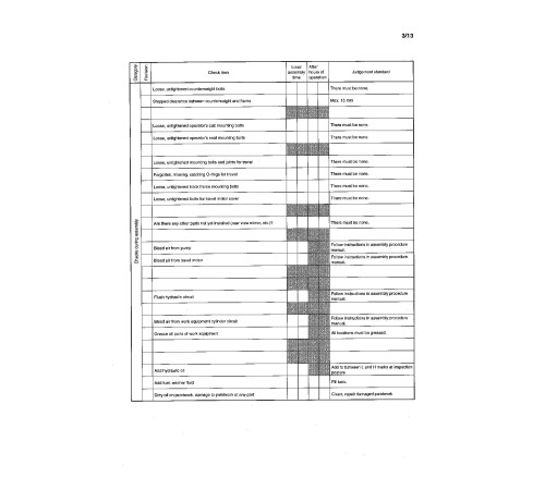
FIELD ASSEMBLY INSPECTION REPORT (BACKHOE)
FIELD ASSEMBLY INSPECTION REPORT (LOADING SHOVEL)
General
Language
EnglishModel of Truck
PC1250-7, PC1250LC-7, PC1250SP-7Region
JapanType of Document
Field Assembly ManualType of Truck
Crawler ExcavatorReviews: 0
There are no reviews for this product.
Questions: 0
No questions about this product.
