

Model
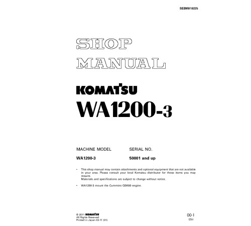
SEBM018225SKU
40797Brand
KomatsuAvailability:
Ready for Instant DownloadThis manual does not contain engine information. Depending on the engine used, see the manuals:
[cummins-QSK60]
$25.00
Language
EnglishModel of Truck
WA1200-3, WA1200-3-ARegion
JapanType of Document
Workshop ManualType of Truck
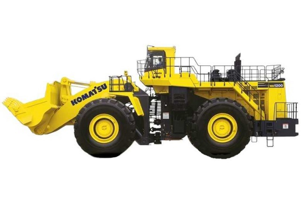
4WD Wheeled LoaderIllustrated factory Workshop Manual for Komatsu 4WD Wheeled Loaders Models WA1200-3 and WA1200-3-A.
This manual will assist you in diagnosing, repairing, and adjusting for your 4wd wheeled loader.
You can use a Windows, Mac, or Android device to view this manual. You only need to have a PDF reader installed.
Covered Models (Japan):
WA1200-3 (SN: 50001-)
WA1200-3-A (SN: 50001-)
Format: PDF, 2398 pages
Language: English
Table of Contents:
GENERAL
GENERAL ASSEMBLY DRAWING
SPECIFICATIONS
WEIGHT TABLE
LIST OF LUBRICANT AND WATER
STRUCTURE AND FUNCTION
OUTLINE
TADIATOR AND HYDRAULIC OIL COOLER
DAMPER
TORQUE CONVERTER AND TRANSMISSION PIPING
TORQUE CONVERTER
MAIN RELIEF VALVE AND TORQUE CONVERTER RELIEF VALVE
TORQUE CONVERTER REGULATOR VALVE
ECMV
TRANSMISSION
TRANSMISSION CONTROL VALVE
LUBRICATING OIL RELIEF VALVE
TRANSFER
TORQUE CONVERTER OIL COOLER
CENTER SUPPORT
AXLE
FINAL DRIVE
AXLE MOUNT
CENTER HINGE PIN
JACK-UP POINT
ARRANGEMENT OF STEERING EQUIPMENT
AJSS (ADVANCED JOYSTICK STEERING SYSTEM)
STEERING PUMP
SWITCH PUMP
SERVO VALVE
STEERING DEMAND VALVE
ROTARY VALVE
EPC VALVE
DIVERTER VALVE
ARRANGEMENT OF BRAKE EQUIPMENT
BRAKE VALVE
HARGE VALVE
ACCUMULATOR (FOR BRAKE)
SLACK ADJUSTER
BRAKE
PARKING BRAKE
PARKING BRAKE OIL CIRCUIT CHECK VALVE ASSEMBLY
ARRANGEMENT OF HYDRAULIC EQUIPMENT
WORK EQUIPMENT LEVER LINKAGE
HYDRAULIC TANK
WORK EQUIPMENT PUMP NO.1
WORK EQUIPMENT PUMP NO.2
WORK EQUIPMENT PUMP NEUTRAL CUT VALVE (NC VALVE)
PPC VALVE (PROPORTIONAL PRESSURE VALVE)
PPC RELIEF VALVE
ACCUMULATOR(FOR PPC VALVE)
MAIN CONTROL VALVE
WORK EQUIPMENT LINKAGE
OPERATION OF PROXIMITY SWITCH
AIR CONDITIONER
MACHINE MONITOR SYSTEM
MAIN MONITOR
CGC MONITOR
MULTI MONITOR
ALL-RANGE ELECTRONIC CONTROL AUTOMATIC TRANSMISSION (ATM) SYSTEM
MODULATED CLUTCH (MOD/C) CONTROL SYSTEM
WORK EQUIPMENT AND JOYSTICK STEERING CONTROL SYSTEM
WORK EQUIPMENT AND JOYSTICK STEERING CONTROLLER
ENGINE STARTING CIRCUIT
ENGINE STOPPING CIRCUIT
ETHER INJECTION CIRCUIT
ELECTRIC PARKING BRAKE CONTROL
PARKING BRAKE SOLENOID VALVE
EMERGENCY PARKING BRAKE RESET SOLENOID VALVE
KICK-DOWN SWITCH AND AUTO SHIFT/MANUAL SHIFT SELECTOR SWITCH
BATTERY DISCONNECTOR SWITCH
EMERGENCY ENGINE STOP SWITCH (FOR RIO TINTO)
HYDRAULIC OIL LEVEL CAUTION DISPLAY (FOR RIO TINTO)
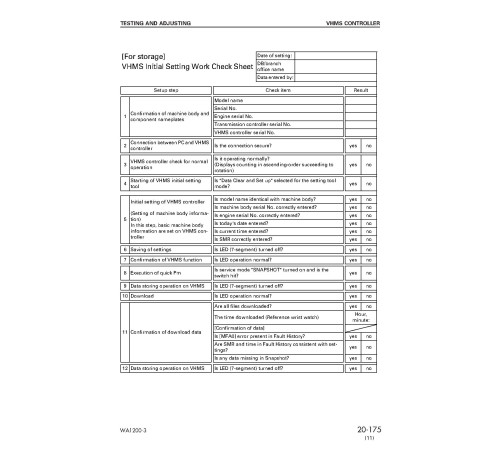
TESTING AND ADJUSTING
STANDARD VALUE TABLE
TESTING AND ADJUSTING
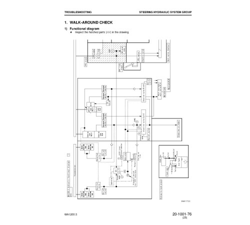
TROUBLESHOOTING
DISASSEMBLY AND ASSEMBLY
How to read this manual
Coating materials list
Special tool list
Sketches of special tools
Procedure for flushing work equipment and steering hydraulic circuit
Procedure for flushing brake hydraulic circuit
Bleeding air from piston pump
Bleeding air from work equipment circuit and steering circuit
Bleeding air from brake circuit
Removal and installation of DT connector pin
Removal and installation of HD connector pin
Repair procedure of HD connector pin harness
Removal and installation of engine assembly
Removal and installation of damper assembly
Disassembly and assembly of damper assembly
Removal and installation of radiator and hydraulic oil cooler assembly
Procedure for disassembly and assembly of MESABI oil cooler assembly
Disassembly and assembly of MESABI oil cooler assembly
Removal and installation of fuel cooler assembly
Removal and installation of torque converter and transmission oil cooler assembly
Removal and installation of bumper and fuel tank assembly
Removal and installation of hood assembly
Removal and installation of bulkhead assembly
Disassembly and assembly of ECMV
Removal and installation of torque converter and transmission assembly
Disconnection and connection of transmission assembly and torque converter assembly
Disconnection and connection of torque converter assembly and PTO • transfer assembly
Disassembly and assembly of torque converter assembly
Disassembly and assembly of modulated clutch assembly
Disassembly and assembly of PTO and transfer assembly
Disconnection and connection of transmission assembly and transfer • parking brake assembly
Disassembly and assembly of transmission assembly
Disassembly and assembly of transfer assembly
Disassembly and assembly of parking brake assembly
Removal and installation of parking brake assembly (from machine body)
Disassembly and assembly of drive shaft assembly
Removal and installation of front axle assembly
Removal and installation of front final drive assembly
Removal and installation of rear axle assembly
Disconnection and connection of differential assembly
Disassembly and assembly of differential assembly
Removal and installation of rear final drive assembly
Disassembly and assembly of final drive and brake assembly
Removal and installation of center support assembly
Disassembly and assembly of center support assembly
Removal and installation of steering demand valve assembly
Removal and installation of steering cylinder assembly
Removal and installation of steering pump, control pump and PPC pump assembly
Removal and installation of switching pump assembly
Removal and installation of emergency diverter valve assembly
Removal and installation of emergency steering pump assembly
Removal and installation of brake accumulator charge valve assembly
Removal and installation of brake oil cooler assembly
Removal and installation of brake oil tank assembly
Removal and installation of transmission, brake cooling and brake pump assembly
Disconnecting procedure for front frame and rear frame
Removal and installation of center hinge pin
Removal and installation of work equipment control valve assembly
Removal and installation of work equipment pump assembly (Right side)
Removal and installation of work equipment pump assembly (Left side)
Removal and installation of hydraulic tank and filter case assembly
Removal and installation of bucket cylinder assembly
Removal and installation of lift cylinder assembly
Disassembly and assembly of hydraulic cylinder assembly
Removal and installation of work equipment assembly
Run-in procedure for bucket pin
Run-in procedure for lift arm pin
Removal and installation of air conditioner unit assembly
Removal and installation of operator`s cab and floor assembly1
Removal and installation of operator`s cab assembly
Disassembly and assembly of operator`s seat assembly
Removal and installation of controller assemblies
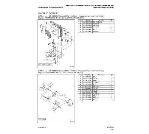
SERVICE KIT PARTS LIST
MAINTENANCE STANDARD
ENGINE MOUNT
TRANSMISSION MOUNT
RADIATOR AND OIL COOLER
DAMPER
TORQUE CONVERTER, TRANSMISSION, BRAKE COOLING AND BRAKE PUMP
INPUT TRANSFER. PTO
MODULATED CLUTCH
TORQUE CONVERTER
TRANSMISSION
TRANSFER
MAINRELIEF, TORQUE CONVERTER RELIEF VALVE
TORQUE CONVERTER REGULATOR VALVE
BY-PASS FILL VALVE
BY-PASS FILL VALVE AND BY-PASS DRAIN VALVE
ECMV
LUBRICATIONG OIL RELIEF VALVE
DRIVE SHAFT
CENTER SUPPORT
DIFFERENTIAL
FINAL DRIVE
AXLE MOUNT
CENTER HINGE PIN
STEERING PUMP
SWITCH PUMP
STEERING DEMAND VALVE
DIVERTER VALVE
STEERING CYLINDER MOUNT
EMERGENCY STEERING PUMP
BRAKE VALVE
SLACK ADJUSTER
BRAKE
PARDING BRAKE
WORK EQUIPMENT PUMP NO.1
WORK EQUIPMENT PUMP NO.2
PPC VALVE
PPC RELIEF VALVE
PUMP CONTROL RELIEF VALVE
MAIN CONTROL VALVE
HYDRAULIC CYLINDER
BUCKET POSITIONER AND REMOTE POSITIONER
BUCKET LINKAGE
OTHERS
TRANSMISSION HYDRAULIC CIRCUIT DIAGRAM
BRAKE CIRCUIT DIAGRAM
WORK EUIPMENT HYDRAULIC CIRCUIT DIAGRAM (1/2) Serial No. : 50001 - 50084
WORK
General
Language
EnglishModel of Truck
WA1200-3, WA1200-3-ARegion
JapanType of Document
Workshop ManualType of Truck
4WD Wheeled LoaderReviews: 0
There are no reviews for this product.
Questions: 0
No questions about this product.
