



$20.00
Generation
3Language
EnglishModel of Truck
FB15H-3, FB18H-3, FB20-2, FB25-2, FB20H-2, FB25H-2, FB20L-2, FB25L-2, FB20S-2, FB25S-2, FB20SH-2, FB25SH-2Region
WorldWideTruck Class
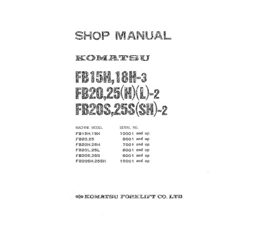
FB15, FB18, FB20, FB25Illustrated factory set of Workshop Manuals for Komatsu Electric Forklift Trucks Models FB15H-3, FB18H-3, FB20-2, FB20H-2, FB20L-2, FB20S-2, FB20SH-2, FB25-2, FB25H-2, FB25L-2, FB25S-2 and FB25SH-2.
This manuals will assist you in diagnosing, repairing, and adjusting for your electric forklift truck.
You can use a Windows, Mac, or Android device to view this manuals. You only need to have a PDF reader installed.
Covered Models:
FB15H-3 (SN: 10001-)
FB18H-3 (SN: 10001-)
FB20-2 (SN: 08001-)
FB20H-2 (SN: 07001-)
FB20L-2 (SN: 06001-)
FB20S-2 (SN: 06001-)
FB20SH-2 (SN: 15001-)
FB25-2 (SN: 08001-)
FB25H-2 (SN: 07001-)
FB25L-2 (SN: 06001-)
FB25S-2 (SN: 06001-)
FB25SH-2 (SN: 15001-)
The manual comprises two Workshop Manuals
1. Workshop Manual (FB15H_25SH.2-BE1)
Format: PDF, 216 pages
Language: English
Table of Contents:
FORWORD
GENERAL
GENERAL VIEWS
SPECIFICATIONS
GENERAL ASSEMBLY DRAWING
SAFETY OPERATION
GENERAL INSTRUCTIONS FOR SAFETY
HANDLING OF REGULAR TOOLS
HANDLING OF HEAVY PARTS
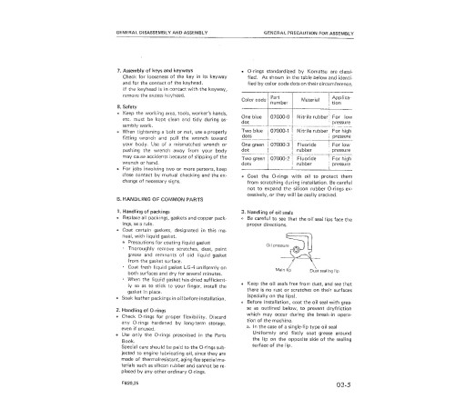
GENERAL PRECAUTIONS FOR DISASSEMBLY AND ASSEMBLY
GENERAL PRECAUTION FOR DISASSEMBLY
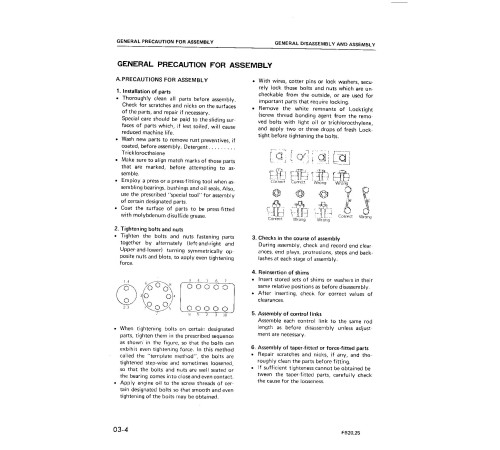
GENERAL PRECAUTION FOR ASSEMBLY
GENERAL PRECAUTIONS FOR CHECKING AND INSPECTION
STANDARD TIGHTENING TORQUE
PERIODIC REPLACEMENT PARTS
REMOVAL AND INSTALLATION OF UNITS
FLOW CHART OF REMOVAL AND INSTALLATION
1.UNITS TO BE REMOVED AFTER DISMOUNTING COUNTERWEIGHT
2.UNITS INSIDE FRAME
3.UNITS OUTSIDE FRAME
4.ELECTRICAL DEVICES
COMMONALITY OF COMPONENT PARTS
DISASSEMBLY AND ASSEMBLY
1.DRIVE SYSTEM
2.STEERING SYSTEM
3.BRAKE SYSTEM
4.WORK EQUIPMENT
ELECTRICAL SYSTEM
GENERAL
STRUCTURE AND FUNCTION
GUARD CIRCUIT
TROUBLESHOOTING
DESCRIPTION
TROUBLESHOOTING GUIDE
WIRING DIAGRAM
TROUBLESHOOTING CHART
CHECKING AND ADJUSTMENT
MAIN CONTROLLER SERVICE DATA
MAINTENANCE PROCEDURE
2. Workshop Manual (FB15H_25SH.2-BE1_SM)
Format: PDF, 228 pages
Language: English
Table of Contents:
GENERAL
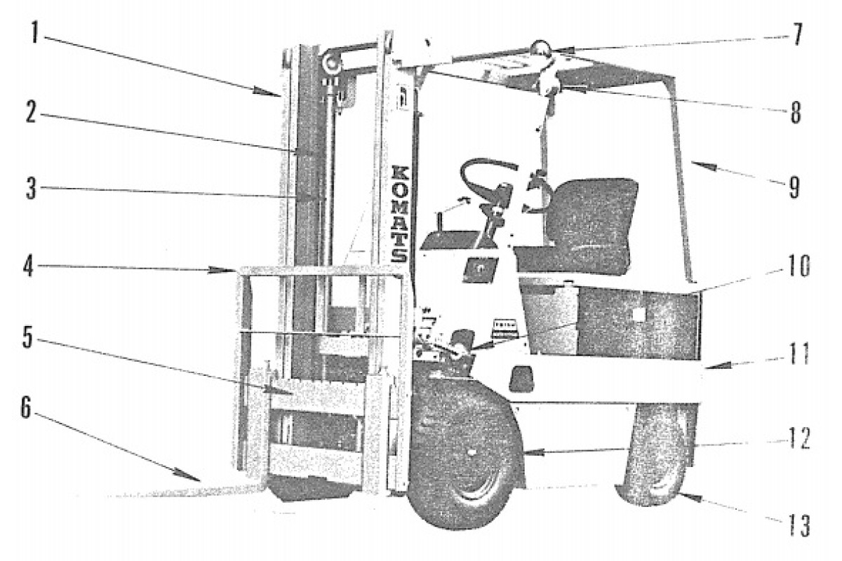
General views
Specifications
General assembly drawing
SAFETY OPERATION
GENERAL PRECAUTIONS FOR DISASSEMBLY AND ASSEMBLY
REMOVAL AMD INSTALLATION OF UNITS
Flow chart of removal and installation
Units to be removed after dismounting counterweight
Overhead guard
Counterweight
Steering axle
Units inside frame
Battery
Power steering cylinder
Hydraulic pump
Pump motor
Power steering motor
Tilt cylinder
Mast
Power train assembly
Steering gear box
Units outside frame
Lift cylinder
Front wheel and rear wheel
Wheel brake
Electrical devices
Wiring diagram
Wiring inside dashboard
Wiring inside main controller
Accelerator
Commonality of component parts
DISASSEMBLY AMD ASSEMBLY
Drive system
General
Transfer
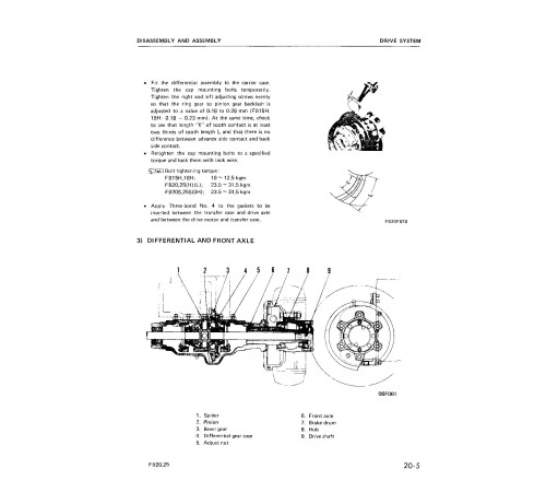
Differential and front axle
Front wheel and rear wheel
Steering system
General
Steering gear box
Power steering cylinder
Rear axle
Brake system
General
Operation of wheel brake
Disassembly of wheel brake
Assembly of wheel brake
Adjustment of wheel brake
Adjustment of air bleeding
Work equipment
Mast
Hydraulic pump
Control valve
Lift cylinder
Dowri control valve and safety valve
Tilt cylinder and power steering cylinder
ELECTRICAL SYSTEM
General
Construction of electrical system
Structure and function
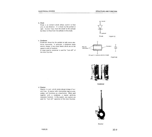
Principle of drive motor speed control ...
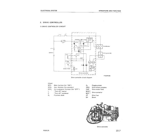
Drive controller
Fuse
F-R controller
Accelerator
Travel control operation
Pump contactor
Power steering contactor
Guard circuit
TROUBLESHOOTING
Description
Troubleshooting guide
Wiring diagram
Troubleshooting chart
CHECKING AND ADJUSTMENT
Main controller service data
Maintenance procedure
General
Generation
3Language
EnglishModel of Truck
FB15H-3, FB18H-3, FB20-2, FB25-2, FB20H-2, FB25H-2, FB20L-2, FB25L-2, FB20S-2, FB25S-2, FB20SH-2, FB25SH-2Region
WorldWideTruck Class
FB15, FB18, FB20, FB25Type of Document
Workshop ManualType of Truck
Electric Forklift TruckReviews: 0
There are no reviews for this product.
Questions: 0
No questions about this product.
