

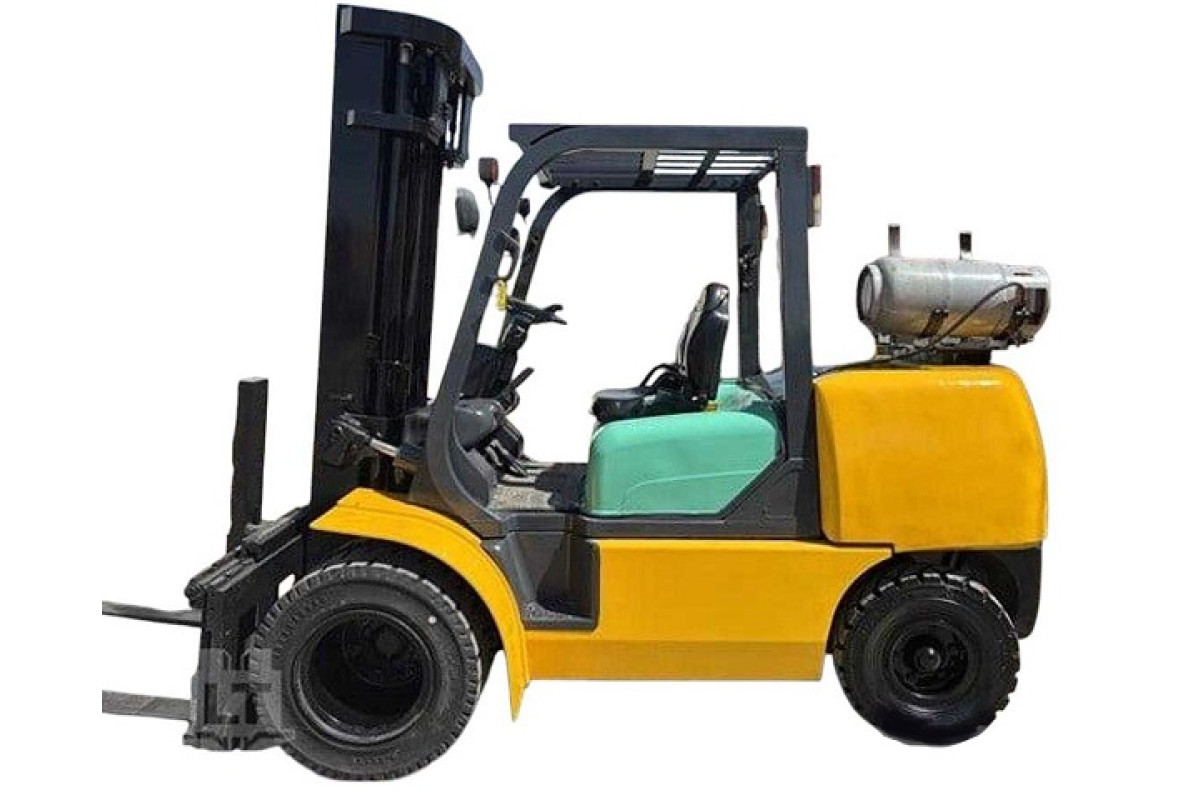
Model
FG50.7_BED08E1-01SKU
42017Brand
KomatsuAvailability:
Ready for Instant DownloadThis manual does not contain engine information. Depending on the engine used, see the manuals: SA6D102E, S6D102E: 6D102E-BE4_SM140 TB42: TB42_SM039
$20.00
Language
EnglishModel of Truck
FG50-7, FG60-7, FG70-7, FD50-8, FD60-8, FD70-8, FD80-8Region
WorldWideType of Document
Workshop ManualType of Truck
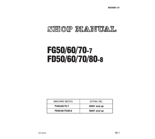
LPG Forklift TruckIllustrated factory Workshop Manual for Komatsu Diesel Forklift Trucks Models FD50-8, FD60-8, FD70-8, FD80-8, LPG Forklift Trucks Models FG50-7, FG60-7 and FG70-7.
This manual will assist you in diagnosing, repairing, and adjusting for your diesel forklift truck or lpg forklift truck.
You can use a Windows, Mac, or Android device to view this manual. You only need to have a PDF reader installed.
Covered Models:
FD50-8 Diesel Forklift Truck (SN: 46001-)
FD60-8 Diesel Forklift Truck (SN: 46001-)
FD70-8 Diesel Forklift Truck (SN: 46001-)
FD80-8 Diesel Forklift Truck (SN: 46001-)
FG50-7 LPG Forklift Truck (SN: 40001-)
FG60-7 LPG Forklift Truck (SN: 40001-)
FG70-7 LPG Forklift Truck (SN: 40001-)
Format: PDF, 336 pages
Language: English
Table of Contents:
FOREWORD
GENERAL AND SPECIFICATIONS
Specifications (FG50-7, FD50-8)
Specifications (FG60-7, FD60-8)
Specifications (FG70-7, FD70-8)
Specifications (FD80-8)
Periodic replacement of consumable parts
Safety items for maintenance
Standard tightening torque
How to use loctite
Conversion table
TESTING AND ADJUSTING
Service data
Gasoline engine
Diesel engine
Air cleaner
Method of adjusting ignition timing
Method of adjusting injection timing
Measuring method for compression
Adjustment method for valve clearance
Tightening torque for cylinder head mounting bolts
Adjusting accelerator pedal
Adjusting brake/inching pedal
Wheel brake
Accumulator for brake
Adjusting parking brake
TORQFLOW transmission case
Differential case
Hydraulic tank
Measuring hydraulic drift of lift cylinder, tilt cylinder
Adjusting mast
Adjusting finger bar
Cooling system
Bleeding air
Specified fuel, lubricating oil, and fluid
Lubricating table
REMOVAL AND INSTALLATION
Unit assembly position
Weight table
Removal and installation flowchart
Overall disassembly and assembly drawing
Lift cylinder
Mast
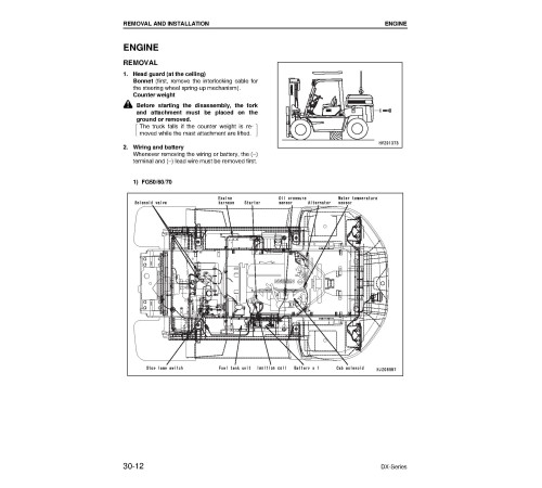
Engine
Torque converter + transmission
Drive axle
Steering axle and power steering
Wheel brake
Standard tightening torque
How to use loctite
DISASSEMBLY AND ASSEMBLY
Disassembly drawing
Torque converter
TORQFLOW transmission
Propeller shaft
Differential
Drive axle (Front axle)
Wheel brake
Parking brake
Steering axle (Rear axle)
Brake pedal
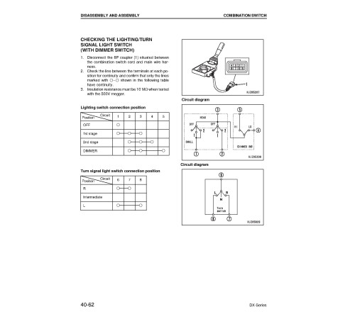
Combination switch
Master back and master cylinder assembly
Brake valve
Steering valve
Hydraulic pump
Control valve
Hydraulic cylinder
Mast
Special tool list
MAINTENANCE STANDARD
Torque converter
Transmission
Transmission control valve
Propeller shaft
Differential
Final drive
Steering axle (Rear axle)
Master back and master cylinder assembly
Brake valve
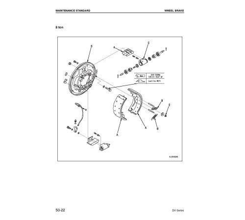
Wheel brake
Parking brake
Hydraulic pump (Single type)
Hydraulic pump (Tanden type)
Power steering cylinder
Lift cylinder
Tilt cylinder
Mast
Control valve
STRUCTURE AND FUNCTION
Power train
Torque converter and transmission control valve
Work equipment control valve
Hydraulic circuit diagram
Brake system
Master back, master cylinder
Brake valve
Assembly drawings
Accelerator pedal (FG50/60/70-7 (TB42 engine))
Accelerator pedal (FD50/60/70-8 (6D102E engine))
Accelerator pedal (FD80-8 (SA6D102E engine))
Brake and inching pedal (5 – 7 ton)
Brake and inching pedal (8 ton)
Parking brake
Torque converter
TORQFLOW transmission
Differential
Front axle (5 – 7 ton)
Front axle (8 ton)
Steering axle (5 – 7 ton)
Steering axle (8 ton)
Brake piping (FD50/60/70-8)
Brake piping (FD80-8)
Work equipment hydraulic piping diagrams (FD50/60/70-8)
Work equipment hydraulic piping diagrams (FD80-8)
Mast
Electrical (5 – 7 ton)
Electrical (8 ton)
Electrical circuit diagram (Gasoline engine truck (TB42 engine))
Electrical circuit diagram (Diesel engine truck (S6D102E engine, FD50, 60, 70-8))
Electrical circuit diagram (Diesel engine truck (SA6D102E engine, FD80-8))
Speedometer (option)
Hinged fork (For 5 – 6 ton models, fixed guard type: HFF607)
Side shift (For 5 – 6 ton models: FSE607)
Clamp base (For 5 – 6 ton models: CBW607) .
TROUBLESHOOTING
Engine
Electrical system
TORQFLOW system
Steering system
Brake system
Hydraulic system
CHECK ITEMS FOR EACH EQUIPMENT
Engine
Power train
Travel system
Steering system
Braking system
Load system
Hydraulic system
Body safety system, Overall test.
General
Language
EnglishModel of Truck
FG50-7, FG60-7, FG70-7, FD50-8, FD60-8, FD70-8, FD80-8Region
WorldWideType of Document
Workshop ManualType of Truck
LPG Forklift TruckReviews: 0
There are no reviews for this product.
Questions: 0
No questions about this product.
